
In the previous article, we had discussed the what is a VMS and the application of a VMS. Today, we will discuss about the steps to operate the VMS and things to know during the operation. To operate VMS, we need to understand the basic of computer-aided-drawing (CAD) and metrology to ensure the best measurement results. The measurement process of VMS is mainly based on the metrology software as most of the features are only accessible via the software. Now, let us see what the procedures is to perform measurement on VMS.
First, run the metrology software after powering on the computer and the VMS. For motorised VMS such as ULTRA series, the software will prompt a message “Sure to find worktable Ref?” during the start up. It is for the computer to find machine coordination to ensure the measurement is accurate and consistent. If yes is selected, the worktable will be moved automatically to the origin.
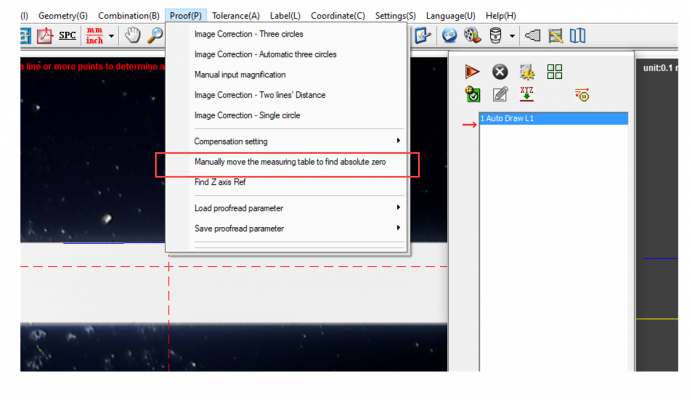
Meanwhile, for manual VMS such as BASIC series, we need to click the “Manually move the measuring table to find absolute zero” under “Proof(P)” in the taskbar. We need to manually move the worktable right and left, backward and forward by rotating the travel knobs as instructions. The program will find the machine coordinate automatically.
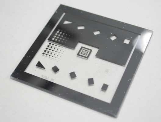
Next, we need to perform the image correction. It is recommended to perform the image correction for the first operation or operation after a long while to allow the computer to acquire the scale of measuring object’s pixel and actual size. For the image correction, we will need to place the calibration glass on the worktable of the VMS.
Then, adjust the zoom lens and lighting of the to make sure the image of the calibration glass is clear and easy to be observed with the lighting control panel at the bottom. If it is not there, click on the bulb icon in the command window. To make the lining and edges of the image clear, it is advised to make the object contrast to the background.
![]()
For image correction, we need to click the “Image Correction – Three Circles” under “Proof” in the taskbar.
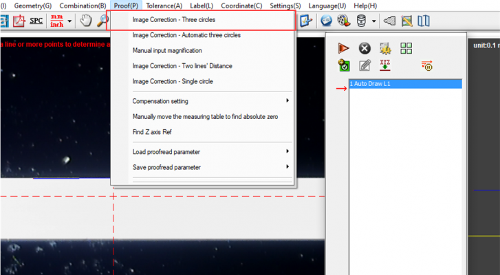
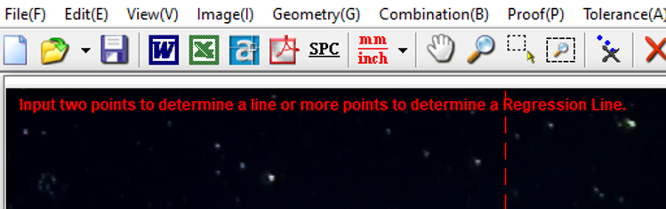
Select a proper size standard circle on the calibration glass and move the circle to the three-indication area of video zone. When the circle is at the indicating area, left click respectively and followed by a right click to finish the process. If the alignment is successful, a dialogue box with “correction succeed” message will appear.
Now the VMS is ready to measure. Before the measurement process, there are several steps we need to do:
- Place the sample on worktable,
- Adjust the zoom lens to make sure the image is clear
- Adjust lighting to make the lining and edge clear
- Measure the object with the metrology software
After we get a clear image, we can perform the measurement with the drawing and measuring commands at the bottom. The layout might be a bit different for different user, it can be modified with the “Modify Window Layout” under “View” in the taskbar. Click “Commands Window” to show the commands window.
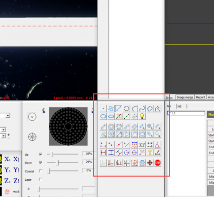
The commands can also be found under the “Image” in the taskbar.
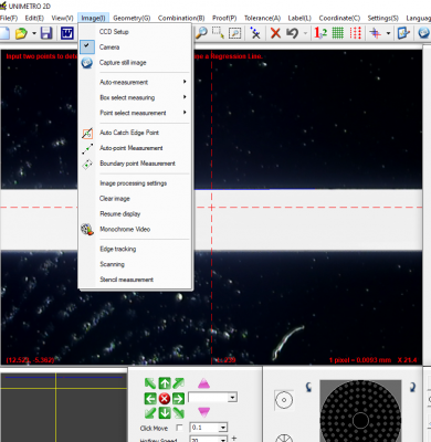
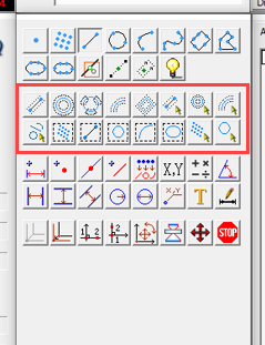
The first two rows are the commands to perform manual plotting such as point, point cloud, line, circle, curve line, s-line, rectangle, polygon and eclipse. Followed by four commands, that are auto catch edge point, auto point measurement, auto boundary measurement and lighting control.
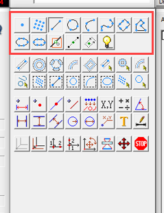
After select a command, there will be a line of instruction shown on top of the camera feed. Plot the line by following the instruction, left click to perform plotting and right click for CAD drawing.
Next, the third and forth row are the commands for automatic detection for line, circle, arc, rectangle and etc. These commands can ease the operation of the plotting, and accelerate the measurement process.
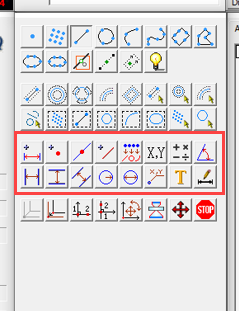
Then, the fifth and sixth row are the commands to do the measurement. We can use these commands to find the length, radius, diameter, angle and also labelling.
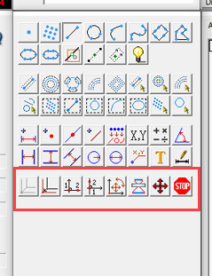
The commands in the last row are to perform axis alignment for the CAD drawing and image focusing. The axis alignment commands are very useful when the sample is not placed upright at the work table. We can use it to define the x-axis and y-axis. The image focusing is to enhance the image for better observation of line and shape.
Besides, the VMS can be pre-programmed to perform automatic measurement. This function only applicable to the motorised VMS and it is very convenient for bulk measuring.

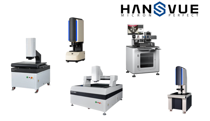
Let’s use our HANSVUE VMS accelerate and improve your quality assurance process.
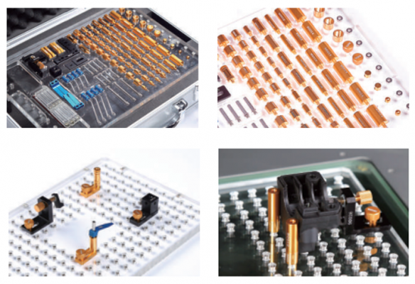
For a better user experience, operator can add-on a fixture/jig to hold the objects in order to ensure it sample do not move around and affect the accuracy of the measurement results. For more specification and procedure of the VMS, kindly refer to the brochure/user manual.
If you have any enquiry or interested to know more about our products and services provided, please don’t hesitate to contact us ([email protected]).