Description
GL7000 specifications
| Item | Description | |
|---|---|---|
| Model number | GL7000 | |
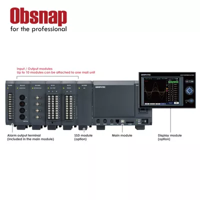
| Number of module | Attached to up to 10 modules (*1) | |
| Number of input channels | Max. 112 channels in 1 of GL7000 | |
| External Input/Output signals (*2) | Input | Start/Stop, External trigger, External sampling, Auto balance (*3) Signal type: Contact (relay), Open collector, Voltage |
| Output | Trigger, Busy (*3), Alarm (10 channels) (*4) Signal type: Open collector (pulled-up by resistor 10 kΩ) |
|
| Trigger, Alarm function | Trigger action | Start or stop capturing data by the trigger |
| Trigger repeat | Enabled (ON): Automatically re-armed for the next data capture function Disabled (OFF): Data capture is completed in a single trigger (Hold off repeat action in specified period: Previous start to next start, previous stop to next start) |
|
| Trigger source | Start: Off, Measured signal, Alarm, External signal, Clock, Week or Time Stop: Off, Measured signal, Alarm, External signal, Clock, Week or Time |
|
| Trigger determination conditions for measured signal | Combination: OR or AND condition at the level of signal or edge of signal Analog: Higher/Rising, Lower/Falling, Window-in, Window-out Logic (*5): Higher/Rising, Lower/Falling Pulse (*5): Higher/Rising, Lower/Falling, Window-in, Window-out |
|
| Alarm determination condition (*6) | Combination: OR or AND condition at the level of signal or edge of signal Analog: Higher/Rising, Lower/Falling, Window-in, Window-out Logic (*5): Higher/Rising, Lower/Falling Pulse (*5): Higher/Rising, Lower/Falling, Window-in, Window-out |
|
| Alarm output | 10 channels | |
| Pre-trigger (*7) | Number of data before trigger: Up to specified number of captured data | |
| Calculation function | Between channels | Addition, Subtraction, Multiplication and Division for two analog inputs (Sampling speed is limited up to 10 Samples/s (100 ms interval). Available arithmetic element and the output destination is the analog input channel 1 to 100.) |
| Statistical | Select two calculations from Average, Peak, Max., Min. in real time and replay (*8) | |
| Move function of the display range | Beginning, center or end of the data, Trigger point, Specific time (absolute, relative), Call cursor | |
| Search function | Search for analog signal levels, logic signal pattern, pulse signal levels or alarm point in captured data | |
| Annotation function | Comment can be set in each channel (up to 31 alphanumeric characters) | |
| Message / Marker Functions | Message: The registered messages or entered message is able to be recorded for any timing. Up to 8 messages can be pre-registered. Marker: Marker is able to record for occurring alarm or power failure. |
|
| Resume | Resume automatically in the same condition after power is recovered as when the power failure occurred during data capture. (*9) | |
| FFT analysis function (Firmware ver. 1.20 or later) |
Analyzing frequency range | 0.08, 0.2, 0.4, 0.8, 1.6, 2, 3.2, 4, 8, 20, 40, 80, 200, 400, 800 Hz, 2, 4, 8, 20, 40, 80, 200, 400 kHz |
| Number of points | 500, 1000, 2000, 4000, 10000 | |
| Window function | Rectangular, Hanning, Hamming, Blackman, Flat-top, Exponential | |
| Averaging | Summation average, Exponential average, Peak hold | |
| Channels | 4 channels | |
| Functions | Y-T, Linear, Power, PSD, Cross, Transfer function, Coherence, COP | |
| Display mode | Single display, Dual display, Nyquist | |
| Interface to PC | Ethernet (10 BASE-T/100 BASE-TX), USB 2.0 (High speed) | |
| Network function | WEB server, FTP server, FTP client, NTP client, DHCP client | |
| USB drive mode | Emulate the USB memory device (*10) | |
| Storage device | Built-in | RAM (2 million samples, built-in amplifier module), Flash memory (4 GB, built-in the main module) (*12) |
| External (*11) | SD card (Support SDHC, up to 32GB) slot, SSD (Approx. 128GB (*12)) The file for capturing data is limited up to 4GB. (*13) |
|
| Data saving function | Sampling speed (interval) | 1 MS/S(1 million samples per second) to 1S/h (1 sample per hour), and synchronized with external sampling signal (Interval: 1, 2, 5, 10, 20, 50, 100, 200, 500 µs, 1, 2, 5, 10, 20, 50, 100, 200, 500 ms, 1, 2, 5, 10, 20, 30, 1, 2, 5, 10, 20, 30 min, 1 hur) * The maximum sapling speed (minimum sampling interval) is different depending on the type of module. * Sampling can be set up to the fastest speed among multiple type connected modules. If the set sampling speed exceeds the fastest speed on module, signal will be sampled and updated at the highest speed of its module and the previous data will be used until the data is updated. * The maximum sampling speed (minimum sampling interval) varies depending on the specified recording destination. |
| Built-in RAM: up to 1 MS/s (1 µs interval) | ||
| SSD module: up to 500 kS/s (2 µs interval) at 1 or 2 modules installed, up to 200 kS/s (5 µs interval) at 3 or 4 modules installed, up to 1 kS/s (1 ms interval) at 5 or 10 modules installed | ||
| Built-in Flash memory: up to 1 MS/s (1 µs interval) | ||
| External SD Flash memory: up to 1 kS/s (1 ms interval) | ||
| Captured data (*11) | Built-in RAM, Built-in Flash, SD memory card, SSD (Data is saved directly to it.) | |
| Data in built-in RAM | Specified number of data up 2 million samples in increments of 1 | |
| Auto save (*11) | Available for the built-in RAM Enabled (ON): Data in the RAM is saved automatically to the built-in Flash, SD memory card, SSD Disabled (OFF): Data in the RAM is not maintained after power is turned off |
|
| Capturing mode (*11) | Mode: Off, Normal, Ring, Relay Ring (*14): Saved most recent data (Number of capturing data: 1000 to 2000000 points, Destination of data: Built-in RAM, Built-in Flash, SD memory card, SSD) Relay(*13)(*15): Saved data to multiple file without losing data until capturing data is stopped (Destination of data: Built-in Flash, SD memory card, SSD) |
|
| During data capture (*17) | Displaying information in two windows, Hot-swapping the SD memory card, Saving data in between cursors. | |
| Backup (*11) | Backup interval (*18): Off, 1, 2, 6, 12, 24 hrs. Data destination (*18): SD memory card, SSD, FTP server Data format (*18): GBD (binary) or CSV (test) Data destination for backup cannot be specified to the same storage for destination of capturing data. |
|
| Dual sampling function (*19) | It enables to record signal with two sampling speed. While the signal is recorded with low speed sampling for long term recording, the transient part is recorded with high speed sampling after the trigger occurs. | |
| Current (low-speed) sampling Recording media:Built-in flash memory or SD card Sampling interval:1, 2, 5, 10, 20, 50, 100, 125, 200, 250, 500ms, 1, 2, 5, 10, 20, 30s, 1, 2, 5, 10, 20, 30min, 1h Trigger timer feature: Starting time, Stopping time, Repeat recording |
||
| Event (high-speed) sampling Recording media:Built-in RAM or SSD (optional) Sampling interval: 1, 2, 5, 10, 20, 50, 100, 200, 500us |
||
| Engineering Scale function | Measured value can be converted to the engineering unit Analog voltage: Converts by four reference points (gain, offset) Temperature: Converts by two reference points (offset) Pulse count: Converts by two reference points (gain) |
|
| Synchronization between units | Start and Trigger (*16) | |
| Accuracy of clock (at 23°C) | ±0.002% (Monthly deviation approx. 50 sec.) | |
| Operating environment | 0 to 40°C, 5 to 85% RH (non condensed) | |
| Power source | 100 to 240 V AC, 50 to 60Hz | |
| Power consumption | 110VA | |
| Standard accessories | Quick guide, CD-ROM, AC power cable | |
| External dimensions (W x D x H) | Main module: Approx. 193 x 141 x 160 mm (Excluding Projection), Alarm output terminal: Approx. 30 x 136 x 145 mm (Excluding projection) |
|
| Weight | Main module: Approx. 2.2 kg, Alarm output terminal: Approx. 350 g | |
